|
A Cube of Resistors |
|
|
|
I have squandered my resistance for a pocket full of mumbles… |
|
Paul Simon |
|
|
|
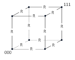
Consider a cubic arrangement of eight vertices, with electrical resistance R along each edge connection as shown below. |
|
|
|
|
|
|
|
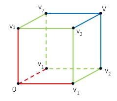
What is the resistance between the vertices marked 000 and 111? If we suppose a voltage V is applied to vertex 111 and a voltage 0 (ground) is applied to vertex 000, then by symmetry the other vertices have one of just two values, which we will call v1 and v2, as shown below. |
|
|
|
|
|
|
|
The current flowing out of the 111 vertex is I = 3(V−v2)/R, and the current flowing into the 000 verrtex is I = 3v1/R. Also, the current flowing from the vertices with voltage v2 to the vertices with voltage v1 is I = 6(v2−v1)/R. These relations imply v1 + v2 = V and 3v1 = v2, from which we get v1 = 2V/5 and hence I = (6/5)V/R. Therefore, the effective resistance between the 000 and 111 vertices is 5R/6. |
|
|
|
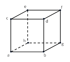
We could take a similar approach, exploiting symmetries, to solve for the resistance between two adjacent vertices, or between two vertices diagonal on a face, but it’s interesting to consider a more general approach. For convenience we designate the verticies with the letters a,b,…,h as shown below. |
|
|
|
|
|
|
|
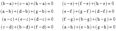
If there were no external connections, the net current into (or out of) each node would be zero, so letting each letter denote the voltage at the respective vertex, and assuming unit resistance on each edge, we have the eight equations |
|
|
|
|
|
|
|
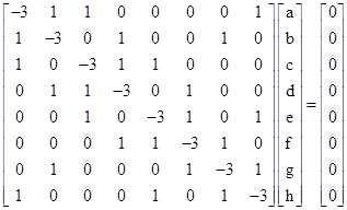
In matrix form this can be written as |
|
|
|
|
|
|
|
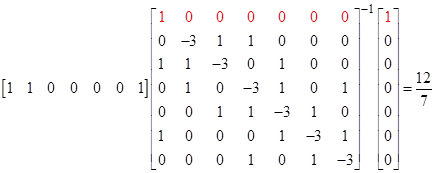
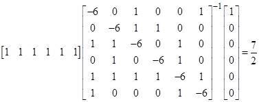
The coefficient matrix is singular, but if we set a = 0 and b = 1, we can delete the first row and column, and replace the “b” row with the equation b=1, and then, noting that the current into vertex a (which is the reciprocal of the effective resistance) is given by b+c+h, we have |
|
|
|
|
|
|
|
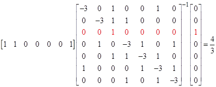
Hence the resistance between adjacent vertices is 7R/12. Likewise to find the resistance between vertices at opposite diagonals of a face, we can replace the “d” row with d=1, which gives |
|
|
|
|
|
|
|
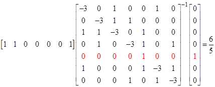
This shows that the resistance between d and a is 3R/4. Lastly, to find the resistance between opposite vertices of the cube, we can replace the “f” row with f=1, which gives |
|
|
|
|
|
|
|
Hence, as we showed previously, the resistance between f and a is 5R/6. By symmetry, these three cases cover all the vertex-to-vertex resistances in the cube. |
|
|
|
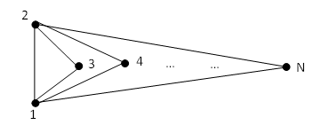
The same approach can also be used to determine the overall resistance between two nodes in a set of N nodes, each of which is connected to each other node by a resistor R. For example, with a set of 7 nodes, each connected to each other by a resistor of resistance 1 ohm, the reciprocal of the overall resistance between any two nodes is |
|
|
|
|
|
|
|
Thus the overall resistance if (2/7)R. Of course, for a complete graph of this kind, with equal resistors on each connection, the high degree of symmetry makes it clear that all the nodes other than the source and sink have the same voltage, and hence there is no current flowing through the resistors between those nodes. So, the effective circuit is just the simple parallel circuit shown below. |
|
|
|
|
|
|
|
If each edge has resistance R, then the overall resistance between vertices 1 and 2 is simply given by the relation |
|
|
|
|
|
|
|
Thus we have the well-known fact that the overall resistance between nodes 1 and 2 (or between any other pair of nodes, since they are all symmetrical) in a complete graph with equal resistors R on each edge is (2/N)R. |
|
|
|
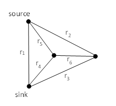
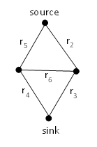
However, if the resistors are not all equal, the result is more complicated. For example, consider the simple tetrahedral circuit shown below. |
|
|
|
|
|
|
|
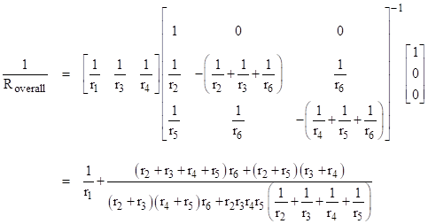
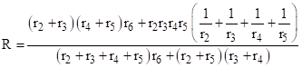
Using the general approach described previously, but with individual resistors for each edge, we get the overall resistance between the source and sink node |
|
|
|
|
|
|
|
With suitable re-labeling of edges, this formula gives the resistance between any two nodes in this complete graph. As a check, notice that if the r6 connection was not present, meaning we have an infinite value of r6, this reduces to |
|
|
|
|
|
|
|
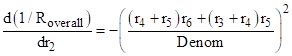
as expected. It’s interesting that the derivative of 1/Roverall with respect to r2 is the negative square value |
|
|
|
|
|
|
|
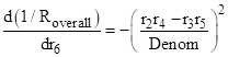
where “Denom” is the denominator of the second fraction in the above general expression for 1/Roverall. Also, the derivative with respect to r6 is |
|
|
|
|
|
|
|
As a consequence, if we meet the condition r2r4 = r3r5, the result is independent of r6, and indeed the expression for the reciprocal of the overall resistance between source and sink reduces (again) to equation (1). |
|
|
|
The preceding results point to an interesting duality between resistance and conductance (the reciprocal of resistance) for the formulas representing some circuits. For example, if we omit the direct connection between source and sink from the circuit discussed above, we get the simple cut diamond circuit (similar to a Wheatstone bridge) shown below. |
|
|
|
|
|
|
|
We know from the preceding discussion that the overall resistance between source and sink is given by |
|
|
|
|
|
|
|
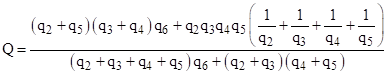
In terms of conductance, we can show by direct substitution Q=1/R and qi=1/ri that |
|
|
|
|
|
|
|
These two expressions have exactly the same form, except for transposition of indices 2 and 4 (or equivalently transposition of indices 3 and 5). If we stipulate that r2 = r4, then the resistance and conductance expressions are formally identical. If we just remove the 2 and 4 links from the circuit, what remains is just three resistors in series, which doesn’t have the duality of expressions, so this might seem puzzling at first, since this is just setting r2 and r4 both equal to infinity. However, the corresponding substitution in the conductance equation is to set q2 and q4 both equal to 0, which reduces to a different formal expression. |
|
|